Tuesday, June 11, 2013
Monday, May 20, 2013
Experiment 16: Determining Plank's Constant
Objective:
Approximate plank's constant with an LED Light circuit.
Equipment:
-LED Lights (green. red, yellow, blue, white)
-2 M Ruler
-Meter stick
-Diffraction grating
-Clamps and stands
-Voltage generator
-Voltmeter
-Resistor
Procedure:
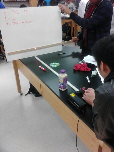
We set up the system as shown in the picture below. We determined the horizontal distance of the LED light's spectrum (similar to previous lab).

The following are the LED light spectra observed through the diffraction grating:


 Conclusion:
Though we got a significantly large error bound, it was to be expected due to the many uncertainties involved in this lab.
Approximate plank's constant with an LED Light circuit.
Equipment:
-LED Lights (green. red, yellow, blue, white)
-2 M Ruler
-Meter stick
-Diffraction grating
-Clamps and stands
-Voltage generator
-Voltmeter
-Resistor
Procedure:
We set up the system as shown in the picture below. We determined the horizontal distance of the LED light's spectrum (similar to previous lab).


Data/Calculations:
We recorded our observations and moved them to an excel sheet the formula used is shown below:


Though we got a significantly large error bound, it was to be expected due to the many uncertainties involved in this lab.
Saturday, May 18, 2013
Experiment 15: Color and Spectra
Objective:
To determine the wavelengths of visible light generated by white light and hydrogen atoms.
Equipment:
-Diffraction grating
-Light source
-Hydrogen gas tube
-1m stick
-2m stick
Procedure:
We set up the system as indicated in the lab manual:


Part I:

Part II:

We observed the diffracted distance and used this to calculate the wavelength using the formula provided in the lab manual.
Data/Calculations:
Derivation of formula used to calculate wavelength:

Part I white light:

We calculated the wavelengths of the longest (red) and shortest (violet) light and compared them with experimental values.
Our theoretical values:

Experimental values:


Comparison:

Part II Hydrogen Spectrum:


Conclusion:
We calculated very precise values using a diffraction grating, which means they are excellent for calculations involving unknown wavelengths emitted from elements in excited states.
Experiment 14: Potential Wells & Potential Energy Diagrams
Part I Potential Wells:
A particle is trapped in a one-dimensional region of space by a potential energy function which is zero between positions zero and L, and equal to U0 at all other positions. This is referred to as a potential well of depth U0.
Examine a proton in a potential well of depth 50 MeV and width 10 x 10-15 m.

Question 1: Infinite Well
If the potential well was infinitely deep, determine the ground state energy. Is this also the ground state energy in the finite well?
E_1(infinite well) = (1)^2(h)^2/(8*(mass of proton)*(10*10^-15) = 2.05MeV
E_1(finite well) = 1.8MeV
The ground state energy of an infinite well is more than the ground state energy of a finite well.
Question 2: First Excited State
If the potential well was infinitely deep, determine the energy of the first excited state (n = 2). Is this also the energy of the first excited state in the finite well?
E_2(infinite) = 4E_1 = 8.20MeV.
E_2(finite) = 6.8 MeV
The energy of the first excited state in the finite well is not the same as the one in the infinite well.
Question 3: "Forbidden" Regions
Since the wavefunction can penetrate into the "forbidden" regions, will the energy of the first excited state in the finite well to be greater than or less than the energy of the first excited state in the infinite well? Why?
The energy in the first excited state in the finite well is less than the first excited state in the infinite well due to the greater probability of tunneling.
Question 4: More Shallow Well
Will the energy of the n = 3 state increase or decrease if the depth of the potential well is decreased from 50 MeV to 25 MeV? Why?
The energy of the n=3 state decreases if the potential well is decreased from 50MeV to 25MeV due to less tunneling.
Question 5: Penetration Depth
What will happen to the penetration depth as the mass of the particle is increased?
As the mass of the particle increases the penetration depth decreases
Part II Potential Energy Diagrams:
A particle of energy 12 x 10-7 J moves in a region of space in which the potential energy is 10 x 10-7 J between the points -5 cm and 0 cm, zero between the points 0 cm and +5 cm, and 20 x 10-7 J everywhere else.

Question 1: Range of Motion
What will be the range of motion of the particle when subject to this potential energy function?
The particle is between +-5 cm.
Question 2: Turning Points
Clearly state why the particle can not travel more than 5 cm from the origin.
The energy that the particle has is less than the energy at the top of the well.
Question 3: Probability of Detection
Assume we measure the position of the particle at several random times. Is there a higher probability of detecting the particle between -5 cm and 0 cm or between 0 cm and +5 cm?
The particle is most likely to be found between -5cm and 0cm because the particle has less kinetic energy at U_1 it moves slower, thus spending more time there.
Question 4: Range of Motion
What will happen to the range of motion of the particle if its energy is doubled?
The range of motion increases
Question 5: Kinetic Energy
Clearly describe the shape of the graph of the particle's kinetic energy vs. position.
The shape is an concave down parabola.
Question 6: Most Likely Location(s)
Assume we measure the position of the particle at several random times. Where will the particle most likely be detected?
The edges.
Sunday, April 21, 2013
Experiment 13: Relativity of Time and Length
Objective:
To observe the effects on time and length that occur as a result of traveling at high speeds.
Data/Calculations:
Relativity of Time


To observe the effects on time and length that occur as a result of traveling at high speeds.
Data/Calculations:
Relativity of Time
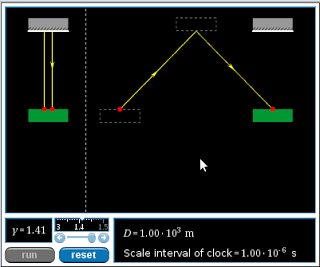
Question 1: Distance traveled by the light pulse
How does the distance traveled by the light pulse on the moving light clock compare to the distance traveled by the light pulse on the stationary light clock?
The time of the stationary clock is longer by a factor of gamma=1.41
Question 2: Time interval required for light pulse travel, as measured on the earth
Given that the speed of the light pulse is independent of the speed of the light clock, how does the time interval for the light pulse to travel to the top mirror and back on the moving light clock compare to on the stationary light clock?
(9.4 – 6.67)*10^-6 s = 2.73 *10^-6 s
The light pulse on the moving clock takes less time than the stationary clock.
Question 3: Time interval required for light pulse travel, as measured on the light clock
Imagine yourself riding on the light clock. In your frame of reference, does the light pulse travel a larger distance when the clock is moving, and hence require a larger time interval to complete a single round trip?
You observe a smaller distance than the stationary observer, therefore, the time is also shorter.
Question 4: The effect of velocity on time dilation
Will the difference in light pulse travel time between the earth's timers and the light clock's timers increase, decrease, or stay the same as the velocity of the light clock is decreased?
The difference between the clocks will decrease.
Question 5: The time dilation formula
Using the time dilation formula, predict how long it will take for the light pulse to travel back and forth between mirrors, as measured by an earth-bound observer, when the light clock has a Lorentz factor (γ) of 1.2.
(6.67*10^-6)(1.2) = 8.004*10^-6s
Question 6: The time dilation formula, one more time
If the time interval between departure and return of the light pulse is measured to be 7.45 µs by an earth-bound observer, what is the Lorentz factor of the light clock as it moves relative to the earth?
7.45*10^-6 = (6.67*10^-6) γ
γ = 7.45/6.67
γ = 1.12
Relativity of Length

Question 1: Round-trip time interval, as measured on the light clock
Imagine riding on the left end of the light clock. A pulse of light departs the left end, travels to the right end, reflects, and returns to the left end of the light clock. Does your measurement of this round-trip time interval depend on whether the light clock is moving or stationary relative to the earth?
No. The light approaches both frames at the same speed.

Question 2: Round-trip time interval, as measured on the earth
Will the round-trip time interval for the light pulse as measured on the earth be longer, shorter, or the same as the time interval measured on the light clock?
The round-trip time interval measured on the earth should be longer.

Question 3: Why does the moving light clock shrink?
You have probably noticed that the length of the moving light clock is smaller than the length of the stationary light clock. Could the round-trip time interval as measured on the earth be equal to the product of the Lorentz factor and the proper time interval if the moving light clock were the same size as the stationary light clock?
The length has to be shorter to accommodate the time difference.
Question 4: The length contraction formula
A light clock is 1000 m long when measured at rest. How long would earth-bound observer's measure the clock to be if it had a Lorentz factor of 1.3 relative to the earth?
l = lo/γ = 1000/1.3 = 769m
Conclusion:
From these simulations we can see that frames moving at high speeds will have slower times and shorter object lengths (length parallel to motion) when compared to stationary or relatively slow frames of references.
Experiment 12: Polarization of Light
Objective:
Observe how light intensity varies through polarizing filters set at predetermined angles.
Equipment:
-Computer
-Logger pro
-Light sensor
-Light source
-3 polarizing filters
Procedure:
Two polarizers:

We set up a system of two polarizers with the light source on one side and the light sensor on the other. We turned the second polarizer to its 90 degree mark and adjusted the first polarizer until the light going through both was as dark as possible, this should occur when the two polarizer axes are perpendicular to each other and assumed the intensity value was as close as possible to zero. We then returned the second polarizer to 0 degrees so that both were parallel and we took intensity measurements in intervals of 7.5 degrees for the second polarizer until we reached a quarter revolution. We then reversed this process and collected further data and created a graph using loggerpro.
Data/Calculations:
two polarizers:

three polarizers:

since the axis for the first and third polarizers are 0 and 90 respectively the intensity will be maximum when the central polarizer is 45 and will be minimum when the central polarizer is either 0 or 90
polarization upon reflection:
- the light from the florescent bulb is unpolarized
- the light in the plane is perpendicular to the light in the table is polarized
Conclusion:
The observed patterns in each case demonstrated how the intensity varies sinusoidally when rotating a polarizer with respect to a light source.
Sunday, April 14, 2013
Experiment 11: CD Diffraction
Objective:
Determine the distance between the grooves on a CD.
Equipment:
-Laser
-CD
-Paper with central hole
-Meter stick
-Clamps
-Stands
-Diffraction grater
Procedure:


We then shone a laser through a small central opening on a piece of paper and recorded the value of the distances from the central maxima.
Data/Calculations:
Wavelength Calculations:

d Calculations:
 Conclusion:
The average value, compared to the standard manufacturer's value of 1600 nm, was smaller by about five hundred nanometers, this means that the manufacturers should look into increasing the distance for the faulty CD's.
Determine the distance between the grooves on a CD.
Equipment:
-Laser
-CD
-Paper with central hole
-Meter stick
-Clamps
-Stands
-Diffraction grater
Procedure:
We shone the laser through a diffraction grater to determine the wavelength.

We then shone a laser through a small central opening on a piece of paper and recorded the value of the distances from the central maxima.
Data/Calculations:
Wavelength Calculations:

d Calculations:

The average value, compared to the standard manufacturer's value of 1600 nm, was smaller by about five hundred nanometers, this means that the manufacturers should look into increasing the distance for the faulty CD's.
Subscribe to:
Comments (Atom)