Sunday, April 21, 2013

Experiment 13: Relativity of Time and Length

Objective:
To observe the effects on time and length that occur as a result of traveling at high speeds.

Data/Calculations:
Relativity of Time

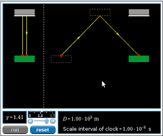
Question 1: Distance traveled by the light pulse
How does the distance traveled by the light pulse on the moving light clock compare to the distance traveled by the light pulse on the stationary light clock?

The time of the stationary clock is longer by a factor of gamma=1.41

Question 2: Time interval required for light pulse travel, as measured on the earth
Given that the speed of the light pulse is independent of the speed of the light clock, how does the time interval for the light pulse to travel to the top mirror and back on the moving light clock compare to on the stationary light clock?
(9.4 – 6.67)*10^-6 s = 2.73 *10^-6 s

The light pulse on the moving clock takes less time than the stationary clock.


Question 3: Time interval required for light pulse travel, as measured on the light clock
Imagine yourself riding on the light clock. In your frame of reference, does the light pulse travel a larger distance when the clock is moving, and hence require a larger time interval to complete a single round trip?

You observe a smaller distance than the stationary observer, therefore, the time is also shorter.

Question 4: The effect of velocity on time dilation
Will the difference in light pulse travel time between the earth's timers and the light clock's timers increase, decrease, or stay the same as the velocity of the light clock is decreased?

The difference between the clocks will decrease.

Question 5: The time dilation formula
Using the time dilation formula, predict how long it will take for the light pulse to travel back and forth between mirrors, as measured by an earth-bound observer, when the light clock has a Lorentz factor (γ) of 1.2.

(6.67*10^-6)(1.2) = 8.004*10^-6s

Question 6: The time dilation formula, one more time
If the time interval between departure and return of the light pulse is measured to be 7.45 µs by an earth-bound observer, what is the Lorentz factor of the light clock as it moves relative to the earth?

7.45*10^-6 = (6.67*10^-6) γ
γ = 7.45/6.67
γ = 1.12

Relativity of Length 

Question 1: Round-trip time interval, as measured on the light clock 
Imagine riding on the left end of the light clock. A pulse of light departs the left end, travels to the right end, reflects, and returns to the left end of the light clock. Does your measurement of this round-trip time interval depend on whether the light clock is moving or stationary relative to the earth?

No. The light approaches both frames at the same speed.


Question 2: Round-trip time interval, as measured on the earth
Will the round-trip time interval for the light pulse as measured on the earth be longer, shorter, or the same as the time interval measured on the light clock?

The round-trip time interval measured on the earth should be longer.


Question 3: Why does the moving light clock shrink?
You have probably noticed that the length of the moving light clock is smaller than the length of the stationary light clock. Could the round-trip time interval as measured on the earth be equal to the product of the Lorentz factor and the proper time interval if the moving light clock were the same size as the stationary light clock?

The length has to be shorter to accommodate the time difference.

Question 4: The length contraction formula
A light clock is 1000 m long when measured at rest. How long would earth-bound observer's measure the clock to be if it had a Lorentz factor of 1.3 relative to the earth?
l = lo/γ = 1000/1.3 = 769m

Conclusion:
From these simulations we can see that frames moving at high speeds will have slower times and shorter object lengths (length parallel to motion) when compared to stationary or relatively slow frames of references.


Experiment 12: Polarization of Light

Objective:
Observe how light intensity varies through polarizing filters set at predetermined angles.

Equipment:
-Computer
-Logger pro
-Light sensor
-Light source
-3 polarizing filters

Procedure:

Two polarizers:


We set up a system of two polarizers with the light source on one side and the light sensor on the other. We turned the second polarizer to its 90 degree mark and adjusted the first polarizer until the light going through both was as dark as possible, this should occur when the two polarizer axes are perpendicular to each other and assumed the intensity value was as close as possible to zero. We then returned the second polarizer to 0 degrees so that both were parallel and we took intensity measurements in intervals of 7.5 degrees for the second polarizer until we reached a quarter revolution. We then reversed this process and collected further data and created a graph using loggerpro.

Data/Calculations:

two polarizers:


three polarizers:

since the axis for the first and third polarizers are 0 and 90 respectively the intensity will be maximum when the central polarizer is 45 and will be minimum when the central polarizer is either 0 or 90

polarization upon reflection:
- the light from the florescent bulb is unpolarized
- the light in the plane is perpendicular to the light in the table is polarized

Conclusion:
The observed patterns in each case demonstrated how the intensity varies sinusoidally when rotating a polarizer with respect to a light source.

Sunday, April 14, 2013

Experiment 11: CD Diffraction

Objective:
Determine the distance between the grooves on a CD.

Equipment:
-Laser
-CD
-Paper with central hole
-Meter stick
-Clamps
-Stands
-Diffraction grater

Procedure:

We shone the laser through a diffraction grater to determine the wavelength.


We then shone a laser through a small central opening on a piece of paper and recorded the value of the distances from the central maxima.
Data/Calculations:
Wavelength Calculations:

d Calculations:
Conclusion:
The average value, compared to the standard manufacturer's value of 1600 nm, was smaller by about five hundred nanometers, this means that the manufacturers should look into increasing the distance for the faulty CD's.

Experiment 10: Measuring a Human Hair

Objective:
To determine the thickness of a human hair using two methods. Measurement through laser diffraction and direct measurement using a micrometer.

Equipment:
-Laser
-Paper (hole punched)
-Micrometer
-Strand of hair
-Meter stick or ruler
-Clamps

Procedure:

For the first part of the lab, we had to turn on the laser and observe the diffraction pattern that resulted on a screen at a set distance.


We then marked the pattern on the whiteboard so we could do the calculations.


For the second part of the lab, we used a micrometer to obtain a value for the thickness of a human hair.

Data/Calculations:

Using the formula y = λL/d for the interference between two slits, we obtained L by measuring the distance from the system to the screen and λ by noting the given wavelength of the laser. We obtained y by measuring the total distance five constructive interference strips (in millimeters) generated and divided this number by five to obtain y, the distance from the first constructive interference maximum (red strip) from the center strip.

For the second part of the experiment, we each took turns measuring the diameter of the hair using the micrometer and we averaged out our values.


We obtained the results on the table below:


Conclusion:
Our results where considerably accurate when we calculated the diameter using the diffraction method, however, the measurements with the micrometer where a lot more accurate than this because this is the micrometer's primary function, therefore, it should be considered closer to the true value. The diffraction method is a lot less accurate because there is a significantly larger source for error in measurements, also, the situation is not an idealized two infinitesimally-small slit interference pattern.


Tuesday, April 2, 2013

Experiment 9: Lenses

Objective:
To observe the characteristics of converging lenses by placing an object on one side of said lens and observing the real, inverted image that is created on the other of the lens.

Equipment;


-Light box
-Converging lens
-Lens holder
-Meter stick
-Index card (or anything else to project the image on)

Procedure:


We determined the focus by having two lasers go through the lens and moving the board onto which they were projected around until they converged into one dot. The distance from this board to the lens was the focus.


For the second part of this experiment, we measured how the object distance affected the image distance and image height and recorded our results on a table. We varied the object distance by moving the lens further away and we obtained an image height by varying the position of the paper the image was projected upon until we could see a clear image.

Lastly, we evaluated what happened to the image when the object distance was at 0.5 f, we concluded that the image went to infinity (diverged).

Data/Calculations:
The table below shows the data we gathered:
We first plotted the image distance vs. the object distance and found that it possessed an inverse relationship:
By plotting the inverse of the image distance vs. the negative inverse of the object distance, we obtain a linear relationship that can be explained by the equation 1/s + 1/s' = 1/f.


Conclusion:
After plotting the inverse values and noticing that the graph is linear, it can be concluded that it is of the form y=mx + b. Substituting what y and x are the equation 1/q = -m/p + b. Comparing it to the standard 1/s + 1/s' = 1/f equation relating object distance s and image distance s' it makes sense that m is equal to 1 and b is equal to 1/f, we obtained a slope of .9 and a y intercept of .184 so we were very close to the actual values. This experiment proves that the object and image distance relationship works. There were some inaccuracies in our experiment and they were accounted for with uncertainties since it was very difficult to get accurate measurements.

Monday, April 1, 2013

Experiment 8: Concave and Convex Mirrors

Introduction:
In this experiment we observed the images created by concave and convex mirrors.

Equipment:
-Convex Mirror
-Concave Mirror
-Object/person

Experiment:
Part A: Convex Mirror


1. Images reflected on convex mirrors had the following characteristics:
-smaller than the original object
-upright
-looked closer relative to the position of mirror and object.

2. As you moved closer, nothing really changed other than the image getting a bit larger due to the fact you were closer to it.

3. The image becomes significantly smaller as you move far away.
Part B: Concave Mirror


1. Objects closer to this type of mirror created images with the following characteristics:
-Image appeared larger than the original object
-The image was upright
-It looked closer than the original object.


2. As you moved closer to the mirror, the image became very distorted and significantly bigger.


3. Distant objects created images with the following characteristics:

-Image appeared smaller than the original object
-The image was inverted
-It looks closer relative to the position of image and object

Data/Calculations:
Part A: Convex Mirror


Part B: Concave Mirror


Conclusion:
Images formed by concave mirrors can vary from being very large and upright to small and inverted while convex mirrors create images that are magnified and remain upright. This is probably due to the fact that the focus is only approachable in the case of the concave mirror.